
Company News


What Is a Printed Circuit Board (PCB)? Types, Structure, and Applications Explained
In modern electronic devices, the printed circuit board (PCB) is a critical foundational component used to support and interconnect electronic components. A PCB consists of a dielectric substrate and conductive copper layers. Electronic components are connected to the circuitry via pads, enabling the transmission of power and signals. Understanding the structure, types, and application value of PCBs is essential for electronic product design, manufacturing, and reliability evaluation.
I. Structural Composition of a Printed Circuit Board
The core structure of a PCB includes the following elements:
Dielectric Material (Substrate)
Common materials include FR-4 (a composite of fiberglass and epoxy resin), as well as polyimide (PI) or metal-based substrates.
The substrate provides mechanical support and electrical insulation, while also influencing the PCB’s thermal performance and signal integrity.
Conductive Layers (Copper Traces)
Copper layers are patterned through processes such as photolithography and etching to form signal traces and planes for signal routing and power distribution.
PCBs may be single-layer, double-layer, or multilayer boards. Multilayer PCBs achieve more complex electrical interconnections through internal routing layers.
Bonding and Insulation Layers
In multilayer PCBs, internal circuit layers are bonded together using insulating prepreg materials and adhesive layers through a lamination process, forming an integrated structure.
Pads, Solder Mask, and Silkscreen Layers
Pads are used for component mounting and soldering.
The solder mask prevents solder bridging and short circuits.
The silkscreen layer marks component locations, reference designators, and identifiers.
Note: Signal integrity and EMI suppression depend not only on low-loss materials, but also on proper routing, ground plane design, and impedance control.
II. PCB Reliability and Application Classification
PCBs are used across a wide range of applications, each with different reliability requirements. In practice, the industry typically refers to the IPC-601x series standards rather than a simple “Class 1, Class 2, Class 3” distinction.
General-purpose PCBs:
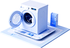
Used in consumer electronics such as smartphones, computers, and home appliances, with an emphasis on cost control and basic reliability.
High-reliability PCBs:
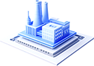
Applied in industrial control and communication equipment, requiring low failure rates and long-term operational stability.
Safety-critical PCBs:
Used in aerospace, medical devices, and similar fields. Manufacturing and testing standards are extremely stringent, as any failure may result in severe consequences.
III. Main Types of Printed Circuit Boards
Based on substrate materials and performance characteristics, PCBs can be categorized into rigid PCBs, flexible PCBs, and metal-core PCBs:
1. Rigid PCBs
Manufactured using FR-4 or other high-performance epoxy fiberglass substrates, with circuitry formed via photolithography and etching processes.
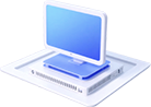
Commonly used in computer motherboards, industrial control systems, and household appliances.
Characteristics: High mechanical strength and dimensional stability, but non-flexible.
2. Flexible PCBs (FPC)
Use polyimide (PI) or PET films as substrates, with copper circuits formed through photolithographic processes.
They can be bent, folded, or rolled, with typical thicknesses ranging from 25 to 125 µm.
Widely used in wearable devices, mobile terminals, and space-constrained layout designs.
3. Metal-Core PCBs (MCPCB)
Incorporate a metal heat-spreading layer (aluminum or copper) beneath the rigid substrate. Heat from high-power components is transferred through an insulating layer to the metal base.
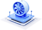
Commonly applied in LED lighting, power modules, and high-power motor control boards.
Characteristics: High thermal conductivity design ensures long-term stable operation and improved thermal management.


Copyright © 2025 COSMOPlat. All Rights Reserved. 鲁ICP备2023031763号
Call us if you have any questions or suggestions: 400-135-7277